RBD Block Types
In order to provide the flexibility required to create RBDs that model actual systems as realistically as possible, there are several different types of blocks that you can use in your diagrams. For the different types of blocks, the appearance and options available in the Block Properties window will vary. This section is intended to help you identify the basic types of blocks found in RBDs.
Note: The shapes, colors and locations shown here represent the default settings. For information on modifying appearance settings, see Diagram Skins and Appearance Settings.
|
|
Standard blocks represent some functional portion of the system, such as a component, subsystem, assembly or failure mode. |
|
|
|
A block that is circular in shape is a node block. Node blocks allow you to construct k-out-of-n configurations. In these configurations, a specified number of paths must reach the node without failing in order for the system to be successful. |
|
|
|
A block that is in the shape of a folder indicates that the block represents an existing diagram. |
|
|
|
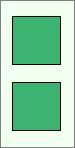
A block that is gray and has an opening in its border is a standby container, which allows you to identify blocks that operate in a standby configuration. The blocks inside the container describe the characteristics of the items that operate together in the standby configuration. |
|
|
|
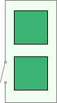
A block that is gray and has a solid border is a load sharing container, which allows you to identify blocks that operate in a load sharing configuration. The blocks inside the container describe the characteristics of the items that operate together in the load sharing configuration. |


For standard blocks, there are several status indicators that may appear on the block. Although each status is presented individually for demonstration purposes, a single block can be defined with more than one type of status.
|
|
Inactive Block |
An X through the block indicates that the block is inactive for reliability calculations (i.e., set to "off"). This is done by selecting the Set block as failed option in the Block Properties window or by selecting the block in the diagram and choosing [Diagram/Fault Tree] > Settings > Set Block as Failed. This option can be used for "what-if" analyses to investigate the impact of a block on system metrics such as reliability, availability, throughput, etc. |
|
|
Block Belongs to a Maintenance Group |
A red circle in the upper left corner indicates that the block belongs to a maintenance group. A maintenance group is a set of blocks where some event within the group can trigger either maintenance or state changes for one or more blocks, either within the group or outside of it. Clicking the indicator opens the Maintenance Group Manager. You can change the size of the indicator via the relevant Block Corner Indicators page of the Diagram Style window. You can change the color used for each maintenance group via the Maintenance Group Manager. |
|
|
A gray box in the lower left corner indicates that the block is a mirrored block. The mirror group to which it belongs is displayed beside the box. All blocks in the mirror group represent the same component in more than one location. Clicking the indicator opens the Mirror Group Manager. You can change the size of the indicator and the appearance of the text via the relevant Block Corner Indicators pages of the Diagram Style window. You can change the color used for each mirror group via the Mirror Group Manager. |
|
|
|
Block Has State Change Triggers Enabled |
A blue diamond in the lower right corner indicates that the block has state change triggers enabled. State change triggers allow you to specify events that will activate and/or deactivate the block during simulation. You can change the size and color of the indicator via the relevant Block Corner Indicators page of the Diagram Style window. |
|
|
Multi Block |
A block that appears to be a stack of blocks indicates that the block represents more than one block with the same properties. These blocks can be configured in series or parallel. The settings are specified by selecting the Represents multiple blocks option in the Block Properties window. |


Additionally, any block type may show the following indicator.
|
|
Block Has Attachment(s) |
An attachment icon in the upper right corner indicates that the block has one or more attachments. You can change the size of the indicator via the relevant Block Corner Indicators page of the Diagram Style window. |
