Standard Blocks and Basic Configurations
Standard blocks represent some functional portion of the system, such as a component, subsystem, assembly or failure mode. Using only standard blocks, you can define series configurations, parallel configurations and combinations of the two, as well as complex configurations.
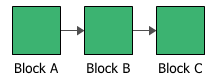
In a series configuration, all items must work for the system to work. In the RBD shown next, the system fails if either Block A, Block B or Block C fails.
The ReliaWiki resource portal has more information on series configurations at: http://www.reliawiki.org/index.php/RBDs_and_Analytical_System_Reliability.
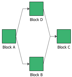
In a parallel configuration, items are considered to be redundant. In the RBD shown next, the system will continue to function if either Block D or Block B fails.
The ReliaWiki resource portal has more information on parallel configurations at: http://www.reliawiki.org/index.php/RBDs_and_Analytical_System_Reliability.
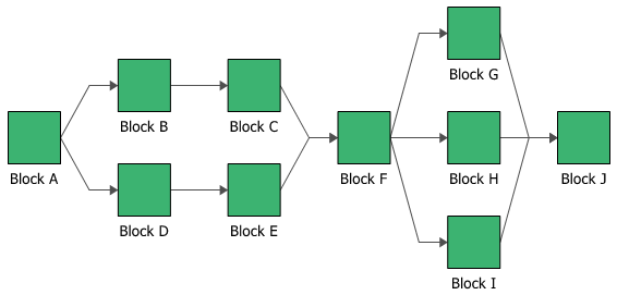
You can combine series and parallel configurations in a single RBD, as shown next.
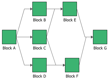
You can also use BlockSim to create "complex" block diagrams. Complex configurations cannot be expressed as a simple combination of series and/or parallel configurations and thus require a more advanced analytical treatment. A complex reliability block diagram is shown next.
Multiple analytical methods exist for obtaining the reliability of a complex system, such as:
- Bayes' theorem method
- Boolean truth table method
- Probability maps method
- Logic diagrams method
- Decomposition method
- Event space method
- Path-tracing method
Solution using these methods is cumbersome and time consuming. BlockSim uses a proprietary method that employs a combination of several of these methods, saving the user time and effort.
The ReliaWiki resource portal has more information on complex configurations at: http://www.reliawiki.org/index.php/RBDs_and_Analytical_System_Reliability.
The properties available for configuring a standard block will vary depending on whether it is in an analytical RBD or a simulation RBD. In addition to the common block properties, you will need to describe how the block behaves.
An analytical diagram does not take into account any repair or maintenance information, so you can configure a standard block in this type of diagram by defining only the reliability characteristics and basic operational properties. In a simulation diagram, you can also define maintenance activities (i.e., a corrective task and/or scheduled tasks), a maintenance group and throughput information. A maintenance group is a set of blocks that can all be maintained at the same time. The throughput properties define the amount of output that can be processed by the block in a given period of time.
The Block Properties window for a standard block is divided into two areas: the Universal Reliability Definition area allows you to define the block's reliability and maintenance characteristics, while the Properties area allows you to define all remaining block properties. By default, the Properties area is on the left side of the window and the Universal Reliability Definition area is on the right side. You can click the Change Orientation icon to toggle the orientation of the areas between horizontal and vertical.
![]()
You can also display only one of the areas or both of the areas by using the following icons to move the splitter all the way to the left/top, to the center, or all the way to the right/bottom.
![]()
![]()
Reliability and maintenance characteristics are defined by assigning a universal reliability definition (URD) in the Universal Reliability Definition area. URDs are resources that can be shared among analyses. Each one includes a model (either a reliability model, a probability of failure model or an event occurrence model) and may also include a corrective task and/or scheduled tasks. When you assign a URD to a block, only those characteristics that are relevant to the block are used. Thus, you could use a URD that includes tasks for a block in either an analytical or a simulation diagram. For the block in the analytical diagram, only the model would be relevant, and all maintenance information would be ignored during analysis. For the block in the simulation diagram, the model and the tasks would be relevant, and all properties would be considered during simulation.
Note: Applying a model that uses a fixed probability to a block causes the block to be considered "static." A static block can be interpreted either as a block with a reliability value that is known only at a given time (but the block's entire failure distribution is unknown) or as a block with a fixed reliability (i.e, a reliability that is constant over time). Systems can contain static blocks, time-dependent blocks or a mixture of the two.
To assign a URD to a block, you can either select an existing URD or create a new one. Click the URD field and then click the arrow to display the URD wizard. In the wizard, you can click Select Existing URD to display a list of the available URDs. You can also click Create New URD to open the Universal Reliability Definition window; in this window, specify the failure model and, if you are working with a simulation diagram, any associated tasks, then click OK to create the new URD and apply it to the block.
Once a URD has been assigned to the block, you can view and/or edit its properties from the URD wizard by clicking the View/Edit icon.
![]()
You can remove the URD from the block by clicking the Remove icon in the URD wizard.
![]()
You can also add, change or edit the components of the URD (i.e., the model, corrective task and/or scheduled tasks) directly from the URD area. Be aware that any changes you make here will apply everywhere that the URD is used.
If no URD is assigned to the block, you can create a new model for the block by clicking the Model field and then clicking the arrow. This opens the Model wizard, which allows you to define a model for the block; this has the effect of automatically creating a new URD that uses the new model and assigning it to the block.
The additional options available to configure the block, located in the Properties area, include:
- Set block as failed if selected, indicates that the block is "off" or absent from the system. An X will be displayed on the block to indicate that it is failed. The block will be considered to be failed throughout the entire analysis/simulation and no maintenance actions will be performed (i.e., any failure and maintenance properties will be ignored). This option can be used for "what-if" analyses to investigate the impact of a block on system metrics such as reliability, availability, throughput, etc. You can also set this option by selecting the block in the diagram and choosing Diagram > Settings > Set Block as Failed.
![]()
When this option is selected, no other properties will be available for the block; note, however, that any properties you have already specified are simply hidden because they are not relevant. The settings will reappear if you clear the Set block as failed option.
- Represents multiple blocks if selected, indicates that the block represents more than one block with the same properties. This can save time in defining and updating block properties, and also save space within the diagram.
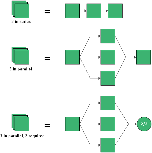
When this option is selected, you can enter the number of components represented by the block and specify whether they are connected in series or in parallel. If they are connected in parallel, you can also specify how many of the items are required to be functioning in order for the multi block to be functioning. The images shown next provide the equivalent configurations for multi blocks representing three blocks in series, three blocks in parallel and three blocks where at least two of the three must be functioning.
IMPORTANT: When a block represents multiple identical blocks, although the components represented by the multi block have the same reliability, maintenance and other characteristics, they are considered separate blocks in analytical diagrams. They will behave comparably over the course of the simulation of a simulation diagram, but not identically at any given time during simulation. For instance, if one of the components fails, the others may continue to function, which can affect when maintenance is performed, costs associated with the block, etc. This is in contrast to the functionality of mirrored blocks. Blocks that belong to a mirror group are multiple instances of a single block. Mathematically, they are considered to be a single block in analytical diagrams. When a simulation diagram with mirrored blocks is simulated, every event associated with one block in a mirror group will also apply to all other blocks in the mirror group.
- Current age defines the age of the block at the start of the analysis. This allows you to define blocks that have already accumulated age (i.e., "used" components). This field requires that you specify a time unit.
- Duty
Cycle allows you to model situations where the
actual usage of a block during system operation is not identical
to the usage for which you have data (either from testing
or from the field). This can include situations where the
item:
- Does not operate continuously (e.g., a DVD drive that was tested in continuous operation, but in actual use within a computer accumulates only 18 minutes of usage for every hour the computer operates).
- Is subjected to loads that are greater than or less than the rated loads (e.g., a motor that is rated to operate at 1,000 rpm but is being used at 800 rpm).
- Is affected by changes in environmental stress (e.g., a laptop computer that is typically used indoors at room temperature, but is being used outdoors in tropical conditions).
In these cases, continuous operation at the rated load is considered to be a duty cycle of 1. Any other level of usage is expressed as a percentage of the rated load value or operating time. For example, consider the DVD drive mentioned above; its duty cycle value would be 18 min / 60 min = 0.3. A duty cycle value higher than 1 indicates a load in excess of the rated value.
The ReliaWiki resource portal has more information on duty cycles at: http://www.reliawiki.org/index.php/Time-Dependent_System_Reliability_(Analytical).
- Consequential Costs allows you to choose or create models to represent costs that are always associated with the block. Cost per failure uses a cost model, and Downtime rate and Uptime rate use cost per unit time models. If no models are assigned, it is assumed that there are no additional costs.
The following additional options are available only when you are working with a simulation diagram:
- Operates even if system is down indicates that the block continues to operate even if the system is down (and will continue to accumulate age).
- Maintenance Group allows you to specify the maintenance group that the block belongs to.
- Enable state change triggers (SCT) allows you to specify the starting state of the block (i.e., off or on) and its state upon repair, then specify events that will activate and/or deactivate the block during simulation. You can choose to activate or deactivate the block when items in specified maintenance groups go down or are restored. The current block does not need to be part of the specified maintenance group to use this functionality. This allows you to model a cold standby configuration (i.e., one where the component cannot fail when in standby) without using a standby container, which may be useful if you are using a parallel or complex configuration, as blocks can be connected only in series in standby containers.
To add a state change trigger, click the Add icon in the Add a state change trigger field. The State Change Trigger window will appear, allowing you to define the trigger. Each trigger that you add will then be displayed in the Block Properties window. To edit an existing state change trigger, click the Edit icon for the state change trigger to open the State Change Trigger window.
- Throughput properties define the amount of output that can be processed by the block in a given period of time.
Once the block is configured, you can click the Optimum Replacement icon in the Properties area to open the Optimum Replacement window for the current block; this window allows you to determine the most cost-effective time to replace the component based on costs for planned (i.e., preventive) and unplanned (i.e., corrective) replacement.
![]()