Standby Containers
Standby containers allow you to identify blocks or paths that operate in a standby redundancy configuration. Each path in the container consists of one or more blocks (connected in series if there is more than one block in the path); one or more of the paths in the container are active while one or more paths are dormant (i.e., standby or quiescent). The dormant paths are available to become active under specified circumstances. In BlockSim, the standby container can also be configured to represent a switch that must be triggered in order to transfer the activity to the standby path (and then back to the original active path, if the standby path later fails or if the original active path is set to be reactivated after repair). Therefore, the standby container can also have an assigned switch that describes the reliability characteristics for the switch (i.e., the probability that the switch will function properly when it is needed) and any maintenance activities that apply to the switch.
For example, suppose that a system contains two batteries but requires only one functioning battery in order for the system to succeed. At any given time, one battery operates while the other waits in a standby state. In addition, the success of the system depends on the successful switch from the active battery to the standby battery, when required. If the active battery fails and there is a successful switch from one battery to the other, then the standby battery becomes active and the system continues to operate. If the switch fails, then the system fails. The system will also fail if the switch is successful but the standby battery has failed while in a standby state.
Note: When analyzing diagrams with containers, the analysis and throughput results are presented at the container level. In addition, optimization via allocation analysis is performed at the container level.
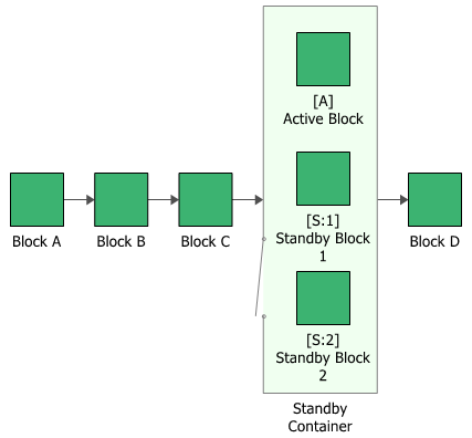
The figure shown next includes a standby container with three items in standby redundancy configuration where one component is active and the other two components are on standby. In this configuration, one block in the container must be operating or, because the container is part of a series configuration, the system will fail.
The container has properties that describe the way the container behaves. A block inside a container, a contained block, also has its own block properties.
To configure a standby container, in addition to the common block properties, you will need to specify the Number of active paths required, which is the number of active paths within the container that must succeed in order for the container to succeed. If the required number of paths does not succeed, then the container is considered to be failed.
Additional options are available for the standby container, including:
- Set block as failed if selected, indicates that the container is failed (i.e., the block is "off" or absent from the system). An X will be displayed on the container to indicate that it is failed. The block will be considered to be failed throughout the entire analysis/simulation and no maintenance actions will be performed (i.e., any failure and maintenance properties will be ignored). This option can be used for "what-if" analyses to investigate the impact of a block on system metrics such as reliability, availability, throughput, etc. You can also set this option by selecting the block in the diagram and choosing Diagram > Settings > Set Block as Failed.
![]()
When this option is selected, no other properties will be available for the block; note, however, that any properties you have already specified are simply hidden because they are not relevant. The settings will reappear if you clear the Set block as failed option.
- Adjust Numerical Convergence Settings opens the Algorithm Setup window, which allows you to modify the parameters of the numerical integration that is used in analyzing the container, as well as to specify a level of accuracy that should be reached during calculations. This option is available only for analytical diagrams.
- The Switch field allows you to create or select a switch resource, which defines the standby container as a switch that is necessary to transfer the activity from active to standby blocks. The switch resource includes information on the reliability of the switch itself and of the switch action, any restarts and any maintenance tasks that apply to the switch.
For standby containers in simulation diagrams, you can also specify throughput properties, which define the amount of output that can be processed by the block in a given period of time.
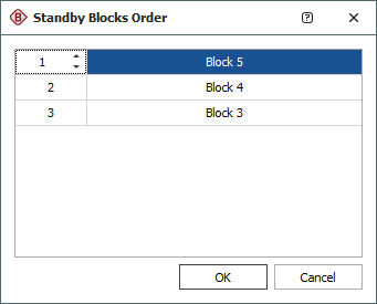
If a standby container has more than one contained block in a standby state, you can specify the order in which the standby blocks are used. To do this, select the standby container and choose Diagram > Properties > Standby Settings > Set Standby Orders or click the Set Standby Orders icon in the Block Properties window for the standby container.
![]()
In the Standby Blocks Order window that appears, the standby blocks are displayed in the order in which they will be used. Select a block and use the up and down arrows that appear in its order number cell to move the block up and down the list. For example, in the window shown next, you would click the down arrow once to move Block 5 down one position; the result would be that Block 4 would be used first, then Block 5, then Block 3.