Subdiagrams
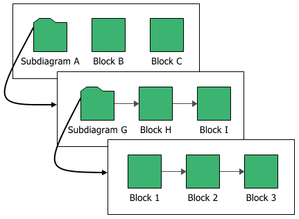
Subdiagram blocks represent other diagrams within the project. Using subdiagram blocks allows you to maintain separate diagrams for portions of a system and to incorporate those diagrams as components of another diagram. This also allows you to generate and analyze extremely complex diagrams representing many subsystems, subsubsystems, etc.
Note: Double-clicking a subdiagram block will open the subdiagram that the block is based on. Open the Block Properties window for a subdiagram block by selecting the block and choosing the command on the ribbon or pressing CTRL+E. To get a quick preview of the subdiagram without actually opening it, select the block and either press SPACE or choose [Diagram/Fault Tree/Phase] > Selection > Quick View.
Subdiagram Block vs. Using a Fitted Model
It is appropriate to use a subdiagram block when you want to take into consideration all properties of all individual blocks in the subdiagram. If you are interested only in the outcome of the subdiagram as a whole (i.e., its fitted distribution and/or system reliability equation), you can create a URD that uses the subdiagram's published results as its failure model; you can then represent the subdiagram within the current diagram by creating a standard block using that URD. You might do this:
- When the subdiagram is a lowest replaceable unit (LRU). That is, when the subdiagram fails, the entire assembly that it represents will be replaced (e.g., a motherboard in a computer).
- In order to represent an analytical subdiagram within a simulation diagram or to represent a simulation subdiagram within an analytical diagram.
- In order to use complex diagrams inside container blocks.
- If your diagram is extremely complex, in order to streamline simulation so that it takes less time.
It is important to remember that in all of these cases, the subdiagram will be treated as an LRU and no results will be available for anything within it.
Selecting the Diagram
To configure a subdiagram block, in addition to the common block properties, you will need to specify the diagram that the subdiagram block represents. You will be prompted for this information when you add the subdiagram block. If you are working with an analytical diagram, only analytical diagrams will be shown in this list; if you are working with a simulation diagram, only simulation diagrams will be available. If the diagram that the subdiagram block will represent has not yet been created, click Create New RBD or Create New Fault Tree .
![]()
![]()
When you are viewing or editing the subdiagram properties in the Block Properties window, you can change the diagram that it represents by choosing an existing diagram from the Based on diagram drop-down list.
Tip: You can drag a diagram from the current project explorer into the current diagram to create a subdiagram block based on that diagram.
Additional Properties
- Represents multiple blocks if selected, indicates that the block represents more than one subdiagrams with the same properties. This can save time in defining and updating block properties, and also save space within the diagram. When this option is selected, you can enter the number of subdiagrams represented by the block and specify whether they are connected in series or in parallel. If they are connected in parallel, you can also specify how many of the items are required to be functioning in order for the multi block to be functioning. (For details, refer to Standard Blocks: Represents Multiple Blocks.) In analytical diagrams, multiple subdiagram blocks cannot refer to diagrams that contain mirrored blocks.
- A maintenance group is a set of blocks where some event within the group can trigger either maintenance or state changes for one or more blocks, either within the group or outside of it. This property applies only in simulation diagrams. When you specify a maintenance group for a subdiagram block, it applies at the subdiagram level rather than to the individual blocks within the subdiagram; for example, the subdiagram block is considered "down" only if some event within it causes the entire subsystem modeled by the diagram to go down.
- A Duty cycle
allows you to model situations where the actual usage of the
assembly represented by the subdiagram during system operation
is not identical to the usage for which you have data. Continuous
operation at the rated load is considered to be a duty cycle
of 1. Any other level of usage is expressed as a percentage
of the rated load value or operating time. (For more information,
see Standard
Blocks: Duty Cycle.)
If a duty cycle is specified for the subdiagram block and there are also duty cycles specified for blocks within the diagram that it represents, their effects are compounded. For instance, if the subdiagram block has a duty cycle of 1.5 and one of the blocks in the diagram that it represents has a duty cycle of 0.75, the effective duty cycle for that block within the subdiagram would be 1.5 x 0.75 = 1.125. - Throughput properties define the amount of output that can be processed by the block in a given period of time. This property applies only in simulation diagrams.