Fault Trees
A fault tree diagram follows a top-down structure and represents a graphical model of the pathways within a system that can lead to a foreseeable, undesirable loss event (or a failure). The pathways connect contributory events and conditions using standard logic symbols.
Fault tree diagrams consist of gates and events connected with lines. The AND and OR gates are the two most commonly used gates in a fault tree. To illustrate the use of these gates, consider two events (called input events) that can lead to another event (called the output event). If the occurrence of either input event causes the output event to occur, then these input events are connected using an OR gate. Alternatively, if both input events must occur in order for the output event to occur, then they are connected by an AND gate. The next figure shows a simple fault tree diagram in which either A or B must occur in order for the output event to occur.
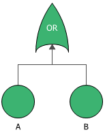
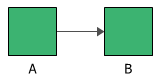
In this diagram, the two events are connected to an OR gate. If the output event is system failure and the two input events are component failures, then this fault tree indicates that the failure of A or B causes the system to fail. The RBD equivalent for this configuration is a simple series system with two blocks, as shown next.
In fault tree analysis, a fault tree diagram is always drawn top-down with the lowest item being an event.
The topics in this section address the following:
- Building fault trees, including:
- Configuring and using blocks in fault trees, including:
Relationship Between RBDs and Fault Trees
The most fundamental difference between fault tree diagrams and RBDs is that you work in the "success space" in an RBD while you work in the "failure space" in a fault tree. In other words, the RBD looks at success combinations while the fault tree looks at failure combinations. Fault trees have traditionally been used to analyze fixed probabilities (i.e., each event that composes the tree has a fixed probability of occurring), and are useful for risk analysis and for analyzing failures and/or pinpointing the root cause of failures. RBDs may include time-varying distributions for the blocks' success or failure, as well as for other properties such as repair/restoration distributions; this makes them well suited for maintainability and throughput analysis, as well as for identifying design weaknesses and performing reliability allocation.
Although the symbols and structures of the two diagram types differ, most of the logical constructions in a fault tree diagram can also be modeled with an RBD. In general, a fault tree can be easily converted to an RBD. It is generally more difficult to convert an RBD into a fault tree, especially if one allows for highly complex configurations.
You can choose Fault Tree > Conversion > Create RBD to create a reliability block diagram that is equivalent to the current fault tree. In addition, you can you can create hybrid analyses by linking fault trees as subdiagrams to RBDs and vice versa.