Inhibit Gates
Inhibit gates allow you to represent a scenario in which the output event occurs if all input events occur and an additional conditional event (typically an event external to the configuration represented by the fault tree) also occurs. An inhibit gate is basically an AND gate with an additional event. An inhibit gate does not really provide any additional modeling capabilities, but is used to illustrate the fact that an additional event must also occur.
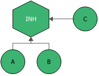
The next figures show fault tree diagram representations of a system in which events A and B must occur as well as a third event, C (the "conditional event"), in order for the system to fail. Traditional fault tree diagrams have the conditional event drawn to the side and the AND gate drawn as a hexagon, as shown next.
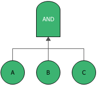
The following figure uses an AND gate with three events, A, B and C. Note that analytically, this representation does not differ from the first figure.
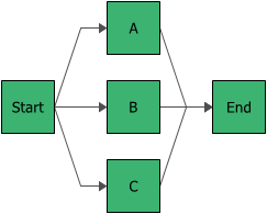
The next figure shows the reliability block diagram representation of the previous fault tree diagrams.
To configure an inhibit gate, in addition to the common block properties, you will need to specify the conditional event. The Conditional event field provides a drop-down list that contains all of the events that are connected to the inhibit gate. You can select which of the events is the additional conditional event (typically an event external to the configuration represented by the fault tree). When you specify the conditional event, it will automatically be moved to the side of the inhibit gate, as shown in the first configuration depicted above.