Standby Gates
Standby gates in fault trees behave just like standby containers in RBDs. The blocks connected to a standby gate are called dependent events and are similar to contained standby blocks in an RBD in that one or more of the dependent events are active while one or more are dormant (i.e., standby or quiescent). Also, just like standby containers, standby gates act as switches that can fail and define the number of active blocks whose failures would cause system failure (or the active vote number required). Additional gates are not allowed below a standby gate.
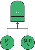
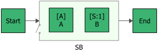
The next two figures show both the fault tree diagram and reliability block diagram representation of a system with two units, A and B, in a standby configuration where unit A is active and unit B is in a standby state.
To configure a standby gate, in addition to the common block properties, you will need to specify the Active vote number, which is the number of events leading to the gate that must succeed in order for the gate to succeed. If the required number of events does not succeed, then the gate is considered to be failed.
Additional options are available for the standby gate, including:
- Set block as failed if selected, indicates that the gate is failed (i.e., the block is "off" or absent from the system). An X will be displayed on the block to indicate that it is failed. The block will be considered to be failed throughout the entire analysis/simulation and no maintenance actions will be performed (i.e., any failure and maintenance properties will be ignored). This option can be used for "what-if" analyses to investigate the impact of a block on system metrics such as reliability, availability, throughput, etc. You can also set this option by selecting the block in the diagram and choosing Fault Tree > Settings > Set Block as Failed.
![]()
When this option is selected, no other properties will be available for the block; note, however, that any properties you have already specified are simply hidden because they are not relevant. The settings will reappear if you clear the Set block as failed option.
- Adjust numerical convergence settings opens the Algorithm Setup window, which allows you to modify the parameters of the numerical integration that is used in analyzing the gate, as well as to specify a level of accuracy that should be reached during calculations. This option is available only for analytical diagrams.
- The Switch field allows you to create or select a switch resource, which defines the standby gate as a switch that is necessary to transfer the activity from active to standby blocks. The switch resource includes information on the reliability of the switch itself and of the switch action, any restarts and any maintenance tasks that apply to the switch.
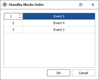
If a standby gate has more than one dependent event in a standby state, you can specify the order in which the standby events are used. To do this, select the standby gate and choose Fault Tree > Properties > Standby Settings > Set Standby Orders or click the Set Standby Orders icon in the Block Properties window for the standby gate.
![]()
In the Standby Blocks Order window that appears, the standby events are displayed in the order in which they will be used. Select an event and use the up and down arrows that appear in its order number cell to move the event up and down the list. For example, in the window shown next, you would click the down arrow once to move Event 5 down one position; the result would be that Event 4 would be used first, then Event 5, then Event 3.