Flowchart Configurations and Execution
Event analysis flowchart simulations are based on the properties of the flowchart blocks, event analysis resources and the configuration of the flowchart. There are almost no inherent limits on the configuration of an event analysis flowchart; this provides you with the flexibility to model any scenario you wish to examine.
In general, each path in the flowchart is placed in a queue, and the simulation executes each path based on its order of priority in the queue. However, there may be situations where the order in which the paths are executed is important to the outcome of the simulation. The following examples demonstrate how to use the advanced configuration settings to control the order of execution.
Tip: Use the Debug tool to run a step-by-step simulation on your flowchart to trace the output and verify whether the flowchart behaves as intended.
Example 1: Blocks with Multiple Outgoing Paths
Consider a block (Block A) that has three outgoing paths. The order of execution of the outgoing paths is based on the connector priority, as shown in the following example. In this case, the path represented by connector 1 will be simulated first, followed by the path for connector 2 and then for connector 3. The simulation continues down each path until it reaches an end, and only then is the next path in the queue executed. A path reaches an end when it is stopped by a block that requires a certain number of executed incoming paths (see Example 2) or it reaches the last block in the path.
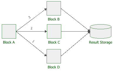
To display or hide the connector priorities, select or clear the Show Connector Priorities check box on the diagram's control panel.
What's Changed? Before Version 9, the Ordered Relations command was used at the block level to show connector priorities.
By default, the connector priority is determined by the order in which the connectors were connected. You can change a connector's priority number by right-clicking the connector and choosing any of the following commands on the shortcut menu: Increase Priority, Decrease Priority, Set to First Priority or Set to Last Priority. You can also specify the priority by choosing Flowchart > Selection > Connector Priority.
![]()
Note the following special cases:
- Conditional blocks and logic gates have advanced configurations that allow you to continue execution on both true and false paths. In this case, the simulation will execute the "true" path first. Once it reaches the end of that path, the simulation will then execute the "false" path and continue until that path also ends.
- Connector priority also applies to subroutines.
The simulation will execute each path in the subroutine queue
until it ends (i.e., makes a full pass through the main flowchart).
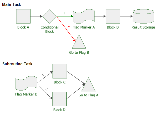
For example, in the following flowchart, the simulation will
execute the subroutine as follows:
- Main Path: Block A → Conditional Block → Go to Flag B → Flag Marker B → Subroutine Path 1 → Subroutine Path 2
- Subroutine Path 1: Block C → Go-to-Flag A → Flag Marker A → Block B → Result Storage.
- Subroutine Path 2: Block D → Go-to-Flag A → Flag Marker A → Block B → Result Storage.
Example 2: Blocks that Require a Certain Number of Inputs
If a block has multiple incoming paths, you can configure the block to not pass an output or compute a result until the block has received a certain number of inputs. This configuration is available for the following blocks:
Enter the desired value in the Required Number of Executed Incoming Paths field in the Block Properties window of the applicable block. Note that this value simply refers to how many inputs are required, and does not distinguish based on which path(s) the inputs come from. For example, if there are three incoming paths and three required inputs, one input from each path would trigger the block, but so would three inputs from the first path.
The following example shows a summing gate that is configured to require 2 inputs before it passes any output to the result storage block. (The connector priorities of the starting block's outgoing paths are also shown to provide context.) In this case, the summing gate will pass two results to the result storage block: once with the value of blocks A+B, and once with the value of blocks C+D.
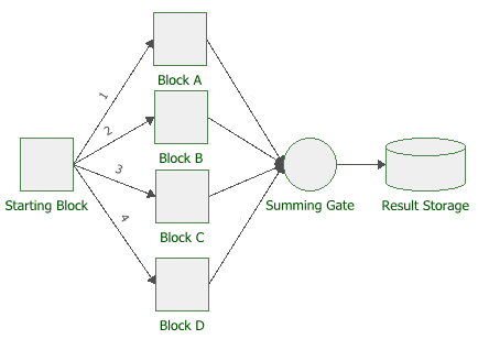
If the summing gate were configured to require 3 inputs, then the result of blocks A+B+C would be passed to the result storage block, and the value from block D would be ignored.
If the summing gate were configured to require only 1 input, then the value of blocks A, B, C and D would be passed to the result storage block, without the summing gate performing any mathematical operation on the values.
Example 3: Flowchart with Multiple Starting Paths
In a flowchart with a single starting path, the blocks are simulated in the order they were added to the path. However, if the flowchart has multiple starting paths, then each path is placed in a queue and executed separately. By default, the simulation executes each path based on the block IDs of the starting blocks. A block ID is a number assigned to the block when it is created. You can display or hide the IDs of all the blocks in a flowchart by selecting the option in the Block ID field on the Background and Grid page of the Diagram Style window.
Note: Block IDs cannot be edited; therefore, to have full control over the execution of a flowchart, we recommend that you add a single starting block to the flowchart and define the connector priorities, as demonstrated in Example 1.
The following example shows a flowchart that has three starting blocks (with the block IDs shown). Each starting block represents an individual path. The starting block with the lowest block ID number has the highest priority in the queue; therefore, in this case, the first path to be simulated is Path 3, followed by Path 2 and then Path 1.
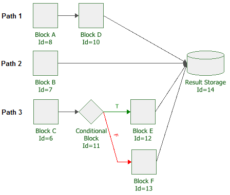
Starting in Version 2019, you can also manually specify the order in which the paths are simulated by choosing Flowchart > Selection > Diagram Actions > Set Path Order.
![]()
In the Path Order window, the paths are indicated by their first blocks.
Note that you can have more than one flowchart within the same diagram, allowing you to test more than one case in the same diagram or create subroutines. The separate flowcharts will be put into the queue based on either the block IDs of their starting blocks or the order specified in the Path Order window.
If your flowchart contains subroutines, you must configure the starting blocks of the subroutines to be executed only when they are called by go-to-flag blocks; otherwise, the simulation will consider the subroutines to be separate flowcharts.