Conditional Blocks
In event analysis flowcharts, a conditional block functions as an "if" statement. It checks the incoming value against a conditional expression, with possible outcomes of true and false. A conditional block accepts one incoming path and may have one or two outgoing paths.
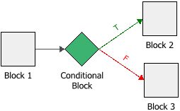
For example, in the configuration shown next, the conditional block evaluates the output from Block 1 against a conditional expression. If the outcome is true, then an output is passed down the "true" (T) path to Block 2, but if the outcome is false, an output is passed down the "false" (F) path to Block 3.
Tip: The software designates the first connector drawn from a conditional block, binary node or logic gate as the "true" path and the second connector as the "false" path. You can switch these designations by right-clicking the connector and choosing Set to Failure or Set to Success on the shortcut menu.
The following picture shows the Block Properties window of the conditional block in the example. In this case, if the output of Block 1 is greater than or equal to 0, then the value "1" is passed down the "true" path. However, if the output of Block 1 is less than 0, then the value 0 is passed down the "false" path.
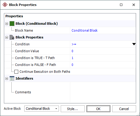
The Condition and Condition Value fields allow you to configure the conditional expression of the block. The drop-down list in the Condition field includes the following relational signs:
|
= |
equal to |
|
<= |
less than or equal to |
|
< |
less than |
|
>= |
greater than or equal to |
|
> |
greater than |
|
FP<=% |
a special case where the conditional block itself draws a random number uniformly distributed from 0 to 100, and then evaluates whether the number is less than or equal to the condition value. |
|
<> |
not equal to |
For the condition value, as well as the outgoing "true" and "false" values, the expression can include:
-
Numerical values
-
Predefined mathematical functions (exp, log, sin, etc.)
-
References to any ReliaSoft Workbooks
You can enter the equation manually, or you can use the function selector or the equation editor to assist you. Resources, ReliaSoft Workbooks and internal functions are automatically color-coded while you are editing the equation, to improve readability.
When the cursor is positioned on a resource, ReliaSoft Workbook or predefined or internal function, a preview area appears and displays a summary of the item. Starting in Version 2019, if a function requires parameters, the preview area indicates (in all capital letters) which parameter you are currently entering; additionally, for nested functions, the preview area displays the current function and the parent function. If the item is a resource, you can click the View icon in the preview area to open that resource's properties window.
![]()
You can enclose a resource name in single quotes to reference it by name. When the item using the expression is transferred to another project or database, any resource referenced by name will not be transferred along with it. If the destination project contains a resource with the same name as the one referenced by name, that resource will be used during simulation of the transferred item. For example, if you export a diagram that contains a block using the expression 'Model1'(1000) from Project1 to Project2, Model1 will not be transferred along with that diagram. If Project2 already contains a model called Model1, that model will be used in simulating the transferred diagram. You can also reference ReliaSoft Workbooks by name.
IMPORTANT: All values and results are assumed to be in terms of the default unit specified for the database. See Using Time Units in Event Analysis Flowcharts for details on how this may affect your analysis.
Advanced Configurations
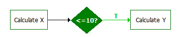
- You can configure the conditional block to have only one outgoing path. This is useful for situations where you want the simulation to end based on a certain condition so that the next simulation, if any, can begin. For example, in the following configuration, if the condition evaluates to true, then the simulation will continue down the "true" path, but if the condition evaluates to false, then the simulation will end because no "false" path exists.
-
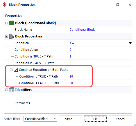
By default, if the condition evaluates to true, then the specified value will be passed down the "true" path and nothing will be passed down the "false" path. Similarly, if the condition evaluates to false, a value will be passed down the "false" path only. If you wish to pass a value down both paths regardless of the outcome of the evaluation, select the Continue Execution on Both Paths check box. This allows you to specify the values to pass to the opposite paths in each case.
In the example shown next, if the incoming value is greater than or equal to zero, the value 1 will be passed down the "true" path and the value 10 will be passed down the "false" path. Similarly, if the condition evaluates to false, the value 0 is will be passed down the "false" path and the value 5 will be passed down the "true" path. (See also Flowchart Configurations and Execution for a discussion on how flowcharts are executed.)