BlockSim Version 2022 Online Help
 Using Fault Trees
BlockSim's fault trees can be
configured as analytical diagrams
(which use the exact mathematical solution for the system model but
impose limitations on what can be modeled and what results can
be obtained) or simulation diagrams
(which provide more modeling options and results but must be analyzed
with discrete event simulation).
Fault trees and reliability block diagrams (RBDs) can be used
together in the same analysis (e.g., a subdiagram block in a fault
tree can point to an RBD and vice versa).
The basic steps for using an analytical fault tree are:
 Add
fault tree diagram
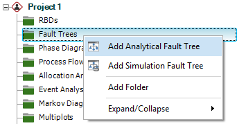
Right-click the Fault Trees folder in the current project
explorer and choose Add
Analytical Fault Tree.
 Add
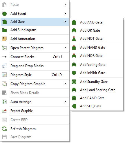
gates
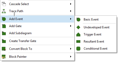
 Add events
Right-click a gate and choose Fault
Tree > Add Event > [Type of Event]. When
a gate is selected, the event will be added below the
gate, already connected.
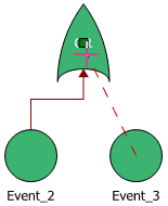
 Connect blocks (if applicable)
If you need to create a new connection, hold down the
ALT key, click
the source block and drag a line to the destination block.
 Set block properties
To edit a block's properties, right-click it and choose
Block Properties.
For gate blocks, you can change the name and identifiers.
For event blocks, specify any operational and cost properties
and use universal reliability
definitions (URDs) to specify the reliability properties.
(See Creating
and Selecting Resources.)
- To select an existing URD, click inside the
URD field.
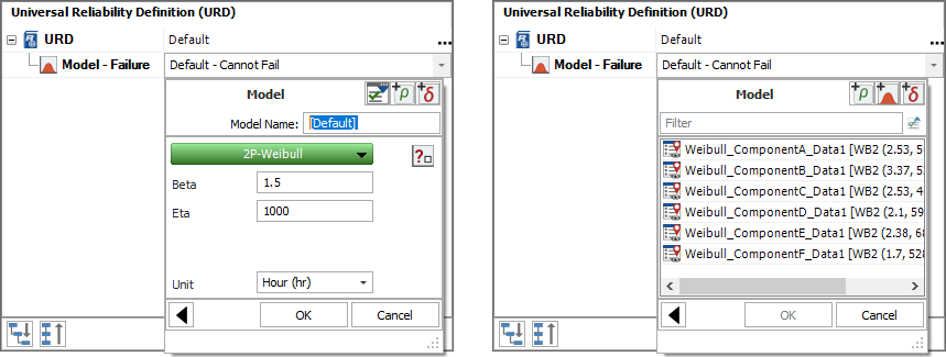
- To create a new URD, click inside the Model - Reliability
field and follow the wizard. You can create a new
model (left) or select an existing model (right).
Existing models may have been manually created, or
may have been published
from other analyses in BlockSim, Weibull++ or
Lambda Predict.
 Analyze the diagram
Click the Analyze
icon on the control panel.

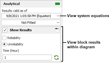
To view the calculated reliability or unreliability
at a specific time for each block, select Show
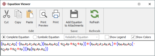
Results on the control panel and specify the time. To view the algebraic equations for the system reliability,
pdf and failure
rate, click the Results
valid as of field on the control panel.
(See Equation Viewer.) Note that starting in Version 2022, you have a choice of analysis methods for analytical fault trees; algebraic equations are available only for the Equation analysis type, not for the new Binary Decision Diagram analysis type. (See Analytical Diagrams.)
 Calculate metrics
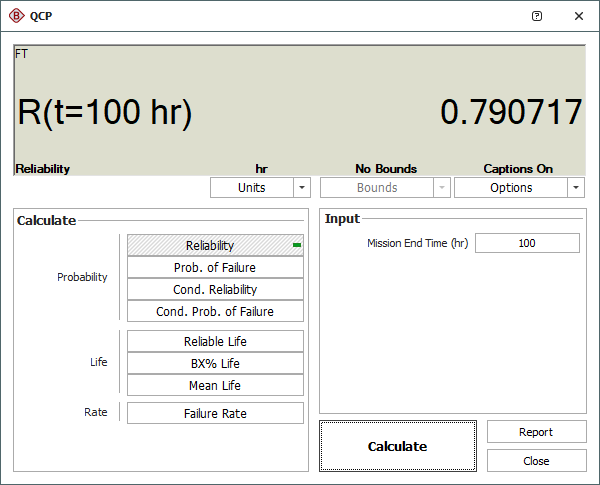
Click the QCP
icon on the control panel to open the Quick Calculation
Pad.
(See Analytical
QCP
for available calculations.)

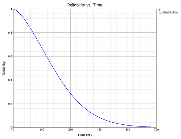
 View plots
Click the Plot
icon on the control panel to open the plot sheet.
(See Analytical Plots
for available plot types.)

 Using Fault Trees
 Add
fault tree diagram
 Add
gates
 Add events
 Connect blocks (if applicable)
 Set block properties
 Analyze the diagram
 Calculate metrics
 View plots

