Connecting Blocks
Connectors represent the flow of the process or system being
diagrammed, and the lines contain information about the relationship
between the specific source and destination blocks that they connect.
Adding Connectors
To add a connector between blocks, you can:
- Right-click the diagram (not blocks) and choose Connect Blocks or choose the command in the ribbon.
- Hold down the ALT key.
In PFS diagrams, use the down arrow on the Connect Blocks ribbon command to specify which flow type you are currently adding before using either of these methods.
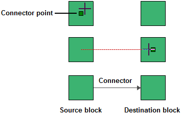
In both methods, the pointer will change to display small crosshairs. Click the source block, hold down the left mouse button and drag a line from the source block to the destination block. When the crosshairs are located over the connection point box, release the mouse button to create a connector.
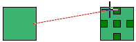
Note that existing connectors can be dragged to different destination blocks, if needed. Also note that the curved, custom curve and custom angled connector types give you the option to connect to the top or bottom of a block, if desired. When this option is available, the blocks will show additional connection point boxes when you create or move a connector.
In BlockSim RBDs, you can add multiple connectors at once by selecting either multiple source blocks or multiple destination blocks and then adding a connector. By default, you will see a message allowing you to choose to add the connections for all of the blocks in the selection. If desired, you can select to stop showing the message in the future and to always perform the action you select going forward. This can be changed in the future by reselecting the Ask for confirmation when connecting multiple blocks option on the Other Settings page of the BlockSim Application Setup. Note that if you clear this option manually within the Application Setup, the default behavior (adding the connection only to the block you actually placed the connector on) will be used.
Starting in Version 20.0.2, you can also connect multiple blocks in fault trees. This adheres to the same constraints that apply to all fault trees; please refer to the topics on each block type (listed here) and to Fault Tree Analysis Constraints for details. No error message is shown for invalid connections when connecting multiple blocks, but only valid connections will be added. The Application Setup option mentioned also above applies in this case.
In fault trees, you will normally connect multiple source blocks to one destination block. If you attempt to reverse this, the software will connect the blocks in the direction that makes logical sense (in much the same way that when you connect a single OR gate to a single OR gate, the gate on top will always be the destination).
Stop Adding Connectors
To stop adding connectors and return the pointer to its normal mode, release the ALT key or click inside the diagram.
Tip: If you do not click the diagram or clear the Connect Blocks option to return the pointer to its normal mode, you will not be able to perform certain other activities, such as moving or deleting blocks. If you are experiencing difficulties with the application, make sure that the pointer is in its normal mode.
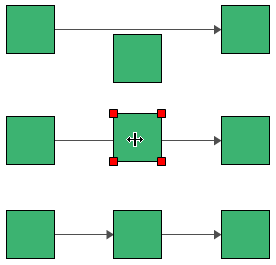
Inserting Blocks/Splitting Connectors
RBDs,
Connector Types
There are several types of connector that can be used in a diagram. The simplest is a straight line but there are options for adding line bends to create curved or angled lines. For details about available connector styles and defining preferences, see Connector Style Settings.
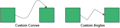
Using Curved, Custom Curve or Angle Connectors
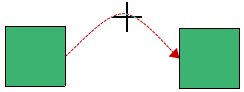
When using curved, custom curve or custom angle connectors, you can choose the location where they connect to the blocks (top, middle or bottom) and add one or more bends to the line. These options can be used separately or in combination.
To add or modify line bends:
- Curved connectors have a single bend point in the center of the connector. To change the angle, click and drag the point to the desired location.
- For custom curve and custom angle connectors, add line bend(s) by clicking anywhere on the connector and dragging the selected point to the desired location.
These custom bends can be removed by right-clicking the connector and choosing Remove all Bend Points or, to remove a single bend point, by right-clicking the bend point and choosing Remove Bend Point.