Reliability of Standby Systems with a Switching Device
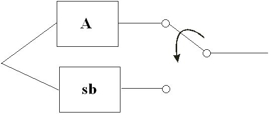
In a previous article, we discussed the case of a system with standby components where a standby component automatically becomes active in the event of the failure of another component in the configuration. However, in many cases when dealing with standby systems, a switching device is also present and required to switch to the standby component in the event of the failure of the active component (as shown in Figure 1). Therefore under such conditions, the failure properties of the switch must also be included in the analysis. This article discusses the failure properties of the switch as well as their incorporation into the analysis and presents an example of such analysis using the BlockSim 6 software.

Figure 1: Standby system with a
switching device
Switch Probabilities
In most cases when the reliability of a switch is to be included in the analysis, two probabilities can be considered. The first and most common one is the probability of the switch performing the action (i.e., switching) when requested to do so. This is called Switch Probability per Request and is expressed as a static probability (e.g., 90%). The second probability is the quiescent reliability of the switch. This provides the probability of success of the switch as it ages. For example, the switch might wear out with age (e.g., corrosion, material degradation, etc.) and therefore the switch might fail before the active component. If the active component does not fail until the mission end time, and the switch fails, then the system does not fail. However, if the active component fails and the switch has also failed, then the system cannot be switched to the standby component and it therefore fails.
In analyzing standby components with a switching device, either or both probabilities can be considered for the switch because, depending on the application, each probability can represent different failure modes. For example, the Switch Probability per Request may represent software related issues or the probability of detecting the failure of an active component and the quiescent reliability may represent wear-out type failures of the switch.
Example
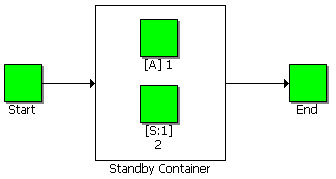
Consider the example given in the previous article, with two components in a standby configuration.

Figure 2: RBD for 2 components in standby
configuration
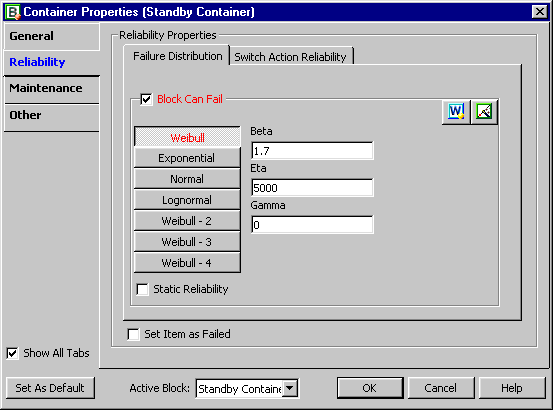
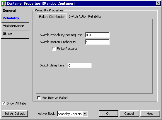
In that example, we assumed perfect switching from standby to active when necessary. In this example, let's examine the effects of including an imperfect switch. Assume that when the active component fails, there is a 90% probability that the switch will transfer from the active component to the standby component. In addition, assume that the switch can also fail due to a wear-out failure mode described by a Weibull distribution with beta = 1.7 and eta = 5000. Note: For this example, we will only consider the non-repairable case, i.e., when a component fails, it is not repaired/replaced.
The reliability of the system at some time, t, can be calculated using the following equation:

Where:
- R1 is the reliability of the active component
- f1 is the pdf of the active component
- R2,sb is the reliability of the standby component when in standby mode (quiescent reliability)
- R2,A is the reliability of the standby component when in active mode
- Rsw,Q is the quiescent reliability of the switch
- Rsw,req is the switch probability per request
- te is the equivalent operating time for the standby unit if it had been operating at an active mode
The BlockSim 6 software can be used to solve for the reliability of this system. After specifying the block properties of the Active and Standby components (as described in the previous article) the following failure properties can be entered for the switch:

Figure 3: Quiescent failure properties for the
standby configuration switch

Figure 4: Probability per Request for the standby
configuration switch
Note that there are additional properties that can be specified in BlockSim 6 for a switch, such as Switch Restart Probability, Finite Restarts and Switch Delay Time. These properties are mostly related to repairable systems and are considered in BlockSim 6 only when using simulation. In this article, we are presenting the analytical solution given by Eqn (1) and these properties are ignored.
The results for the analysis with and without incorporating switch reliability are given in the following table:
| Standby Type | System Reliability at 1000hr without switch (from previous example) |
System Reliability at 1000hr with switch
(from current example) |
| Hot | 0.6004 | 0.5720 |
| Warm | 0.7057 | 0.6635 |
| Cold | 0.8212 | 0.7641 |
Conclusion
From the table above, it can be seen that the presence of a switching device has a significant effect on the reliability of a standby system. So it is important when modeling standby redundancy to incorporate the switching device reliability properties. Note that the methodology presented in this article is NOT the same as treating the switching device as a series component with the standby subsystem. This would only be valid if the failure of the switch would result in the failure of system (i.e., switch failing open). As it can be seen from Eqn (1), the Switch Probability per Request and Quiescent probability are only present in the second term of the equation. Treating these two failure modes as a series configuration with the standby subsystem would imply that they are present when the active component is functioning as well (in the first term of the equation), which is not valid, and the reliability of the system would be underestimated. In other words, these two failure modes become significant only when the active component fails. For example, if we consider the case of the Warm Standby configuration in the table above, the reliability of the system without the switch is 70.57% at 1000 hrs. If we had modeled the switching device to be in series with the warm standby subsystem, then we would get:
Rsys(1000) = Rstandby(1000)*Rsw,Q(1000)*Rsw,req = 0.7057*0.9372*0.9 = 0.5952
So the calculated reliability would have been 59.52% instead of 66.35% (from the table above).
In cases where a switch failure mode that causes the standby subsystem to fail is present, then this mode can be modeled as an individual block in series with the standby subsystem. At the same time, however, if the Switch Probability per Request and Quiescent probability need to be incorporated, this must be done as presented in Eqn (1) of this article.