FMEA Block Diagrams
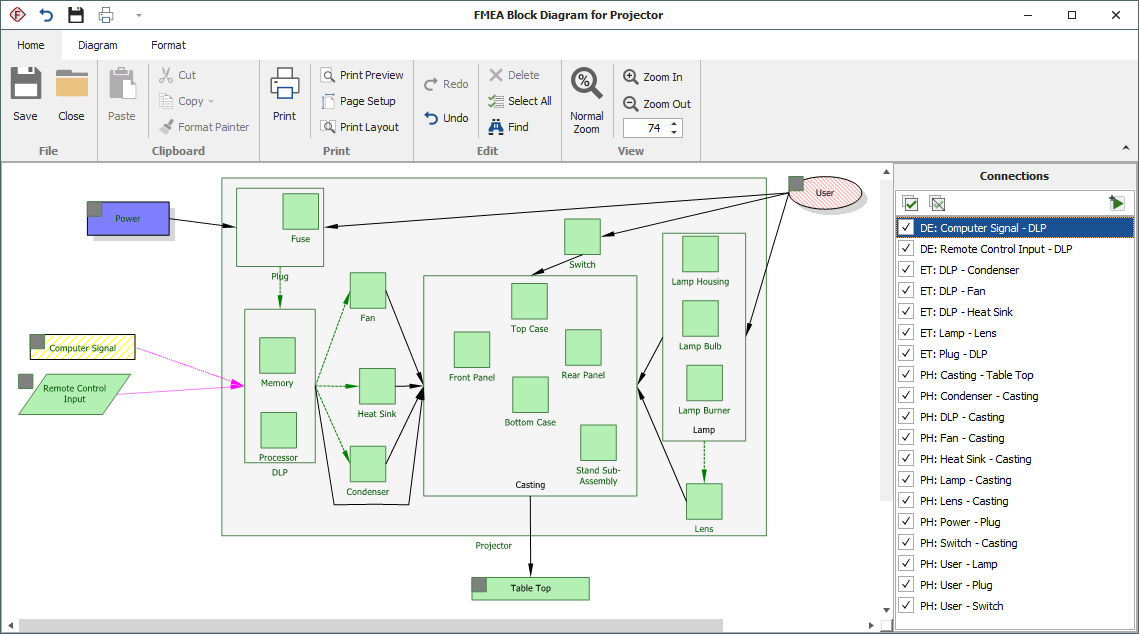
You can create an FMEA Block Diagram for any item in the system hierarchy that visually depicts the system assembly that will be analyzed in a Design FMEA. These diagrams help to define the scope of a particular analysis project and also may provide additional information that will be useful to the analysis team when they attempt to identify potential failure modes.
The FMEA Block Diagram is interactive with both the system hierarchy and the FMEA (if desired). This means that the software will automatically populate the diagram with the components in the selected branch of the system hierarchy. You can then add additional blocks for other factors (e.g., human interactions) and add the appropriate connections (physical, material exchange, data exchange or energy transfer) to complete the diagram. Finally, you can choose to automatically create functions for the selected interactions as a starting point in the FMEA (e.g., "Energy Transfer from Component A to Component B").
Create the FMEA Block Diagram
To create a new FMEA Block Diagram (or open or delete a saved one), select an item in the System panel then choose System Hierarchy > Current Item > Diagrams > FMEA Block Diagram. You can also right-click the item and choose Diagrams > FMEA Block Diagram.
![]()
If a diagram has already been saved for the current item, you will be prompted to open, delete or replace it. (If you are opening a diagram that was created in an earlier version of the software, see Converting Existing Diagrams below.)
The FMEA Block Diagram shows all of the items from the selected branch of the system hierarchy. If an item has sub-items (i.e., an assembly), it will be represented as a container block. If not, it will be represented as a standard block.
You can add blocks to the diagram so that you can add connections that need to be considered in the FMEA. For example, in the image shown below, the "Ground" and "Rider" blocks are not included in the system hierarchy, but were added to the diagram so that their interfaces could be included. The indicator in the top left corner of the block indicates that this is an "Additional Item."
To add a standard block (i.e., an item), choose Diagram > Blocks > Add Block.
![]()
To add a container block (i.e., a next higher level item) , choose Diagram > Blocks > Add Container.
![]()
Add the Connections (Interfaces) Between Items
To add connectors (also known as interfaces), choose Diagram > Settings > Connect Blocks and select a specific connection type. That connection type will be used until you change it.
![]()
You can include up to four separate connectors between blocks, and the same two blocks can be connected in multiple ways.
The default appearance for each connection type is shown here. If you wish to modify the appearance (e.g., add arrowheads to indicate the direction, change the color, etc.), use the Defaults pages in the Diagram Style (which updates all connectors in the diagram that are configured to use default settings) or the Connector Style (which updates only the connector(s) that are currently selected). For more information, seeDiagram Skins and Appearance Settings.
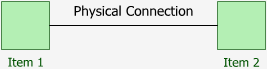
- Physical Connection (PH): The items are attached to each other (e.g., brackets, bolts, clamps and various types of connectors).
- Material Exchange (ME): The items can transfer materials between each other (e.g., pneumatic fluids, hydraulic fluids or any other fluid or material exchange).

- Energy Transfer (ET): The items can transfer energy between each other (e.g., heat transfer, friction or motion transfer such as chain links or gears).
![]()
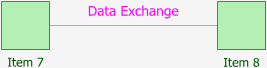
- Data Exchange (DE): The items can transfer data between themselves (e.g., computer inputs or outputs, wiring harnesses, electrical signals or any other types of information exchange).
Create FMEA Functions
The Connections area on the right side of the window lists the connections between the blocks. Use the check boxes to select which connections you want to add as functions to the FMEA for the item, and then choose Diagram > Blocks > Create Functions or click the Create Functions icon.
![]()
The created functions use the following naming convention: [Connection type]: [First item] – [Second item]. Once in the FMEA, you can change the wording as needed.
Converting Existing Diagrams
When opening an FMEA Block Diagram created in Version 9 or earlier version of the software, you will be given the option to update the diagram to the new format:
- If you click Yes, the original diagram displays at the top of the window, similar to how it looked previously. In addition, new diagram blocks that are linked to the system hierarchy are included at the bottom of the window.
- If you click No, the diagram displays the same as it did in the earlier version.