Cause and Effect Diagrams
A cause and effect diagram (also known as a fishbone or Ishikawa diagram) helps you to visualize the relationship among the events described in your analysis. This diagram presents all of the events that lead up to the selected effect or item failure.
To create a new cause and effect diagram for an item (or open or delete an existing one), select the item and choose System Hierarchy > Current Item > Diagrams > Cause and Effect Diagram.
For an effect, choose FMEA > FMEA Records > Effects > Cause and Effect Diagram.
![]()
If the diagram has already been saved for the current item/effect, you will be prompted to open, delete or replace it.
Reading the Cause and Effect Diagram
Although the cause and effect diagram does not have the traditional look of the Ishikawa or fishbone diagram, it can be read the same way. For example, the following diagrams show the events that lead to the failure of System A.
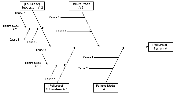
Ishikawa Diagram
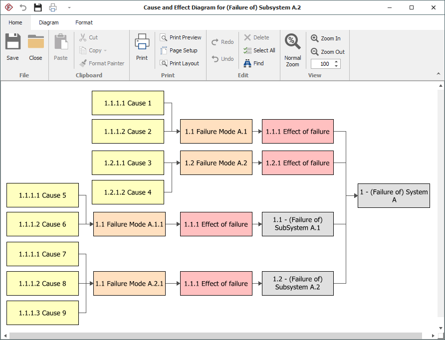
Cause and Effect Diagram for an Item Record
If you create a cause and effect diagram for an effect record, the diagram will consist simply of the failures that lead to that effect and the causes that lead to those failures.
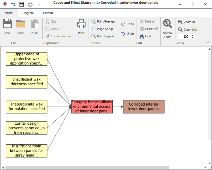
Cause and Effect Diagram for an Effect