PFS Block Types
This section is intended to help you identify the basic types of blocks found in PFS diagrams.
Note: The shapes and colors shown here represent the default settings. For information on modifying appearance settings, see Diagram Skins and Appearance Settings.
|
|
A source block is where a fluid enters the PFS diagram. |
|
|
|
A sink block is where a fluid exits the PFS diagram. |
|
|
|
A process block represents where fluids are combined to create other fluid types. |
|
|
|
A tank block is used to store fluids. |
|
|
|
A valve block is used to switch flow from one output to another. |
|
|
|
A PFS subdiagram block represents another PFS diagram or, starting in Version 2021, simulation RBD within the project. Subdiagrams are generally used to break down a larger diagram into simpler steps to reduce complexity and improve traceability. |
|
|
|
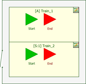
A process standby container allows you to identify paths, or trains, that operate in a standby redundancy configuration. |


Starting in Version 2021, subdiagram blocks in PFS diagrams may show the following indicator.
|
|
Block Represents Non-PFS Diagram |
A blue box in the lower left corner indicates that the subdiagram block represents a simulation RBD instead of a PFS diagram. You can change the appearance of the indicator via the relevant Block Corner Indicators pages of the Diagram Style window. |

Any block type may show the following indicator.
|
|
Block Has Attachment(s) |
An attachment icon in the upper right corner indicates that the block has one or more attachments. You can change the size of the indicator via the relevant Block Corner Indicators page of the Diagram Style window. |
