RBD Configurations and Constraints
BlockSim allows you to create an extensive array of RBD configurations. These can be as simple as units arranged in a pure series or parallel configuration. There can also be systems of combined series/parallel configurations or "complex" systems that cannot be decomposed into groups of series and parallel configurations. The supported configurations include:
- Series configurations, parallel configurations and combined (series and parallel) configurations.
- Complex configurations.
- k-out-of-n parallel configurations.
- Configurations with inherited subdiagrams.
- Standby redundancy configurations.
- Load sharing configurations.
- Configurations with mirrored blocks.
In order to perform analysis, all RBDs created in BlockSim must conform to the following constraints:
- A diagram must contain at least one block.
- If a diagram contains more than one block, all blocks in the diagram must be joined with connectors.
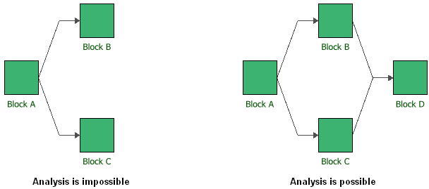
- Diagrams must contain a single starting block and a single ending block, as shown next.

If a diagram consists of only one block, that block represents both the starting and ending block. Starting and/or ending blocks that possess no reliability or maintenance characteristics can be defined by making sure no URD is assigned in the Block Properties window. This indicates that the block cannot fail and that the reliability of the component at all times is considered to be 1 or 100%.
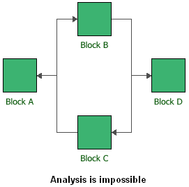
- Circular references, as shown below, are not allowed. There must be a clear path towards the end of the RBD and the RBD cannot loop back on itself.

BlockSim uses a methodology called the Path Tracing Method in order to evaluate the reliability of the system in the RBD. The Path Tracing Method requires that each RBD has one starting block and one ending block. It then calculates all of the "paths" from the starting block to the ending block that would allow the system to function. Circular references are not allowed because they would result in an infinite number of paths through the system.
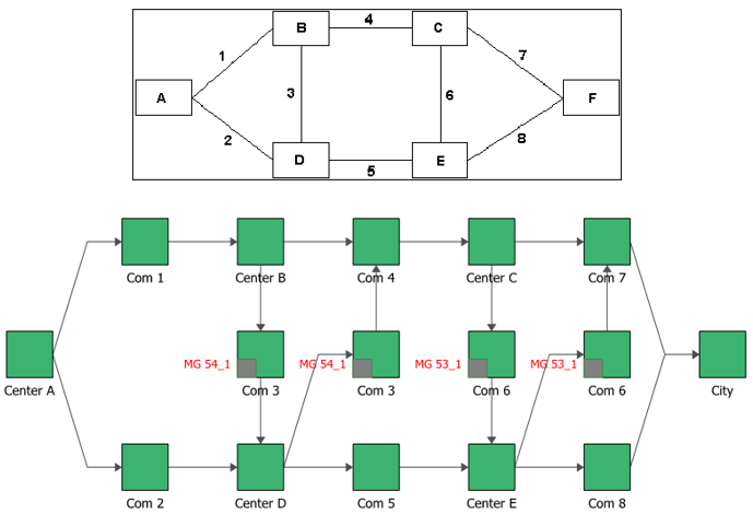
In some circumstances, it may be possible to work around the problem of circular references by using mirrored blocks, which allow you to represent a single item with more than one block placed in multiple locations. Mirrored blocks can be used to simulate bi-directional paths within a diagram. For example, in an RBD for a communications system where the lines can operate in two directions, the use of mirrored blocks will facilitate realistic simulations for the system maintainability and availability. In the RBD shown next, the bi-directionality of Com Line 3 and Com Line 6 is modeled using mirrored blocks. (A mirrored block is indicated by a gray square in the lower left corner of the block.)

- A standby container must contain at least one active block and one standby block.
- A load sharing container must contain at least one block.