Derating for Electronic Components
Derating is a technique usually employed in electrical power and electronic devices, wherein the devices are operated at less than their rated maximum power dissipation, taking into account the case/body temperature, the ambient temperature and the type of cooling mechanism used. In this article, we will briefly explain the theoretical background of derating and how it is applied.
Derating increases the margin of safety between part design limits and applied stresses, thereby providing extra protection for the part. By applying derating in an electrical or electronic component, its degradation rate is reduced. The reliability and life expectancy are improved.
Intuitively, if a component or system is operated under its design limit, it will be more reliable than if it is operated at or above the design limit. Theoretically, the benefit of derating can be explained using load-strength interference theory.
Load-Strength Interference
Usually, failure happens when the applied load exceeds the strength. Load and strength should be considered in a general way. For electronic parts, "load" might refer to voltage, power or an internal stress such as junction temperature. "Strength" might refer to any resisting physical properties.
Electronic components of a given type are not identical. They have strength variability. This variability results from the differences between raw materials and between manufacturing processes. Even for components made from the same materials and by the same processes, differences still exist due to noise factors such as microscopic material defects or variations within a single manufacturing process. Therefore, the strength of a component is considered to be a random variable. The load applied to electronic parts, such as power, temperature or humidity, is also a random variable. Thus, statistical distributions are usually used to describe the load and strength.
Two factors are used to analyze the interference of load and strength distributions. These factors are safety margin (SM) and loading roughness (LR).[1]
Safety margin is defined by:

where L and S are the mean values of the load and strength distributions, and σLand σS are the standard deviations of the load and strength distributions. SM is the relative separation of the mean values of load and strength.
Loading roughness is defined in terms of the standard deviation of the load by:

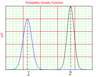
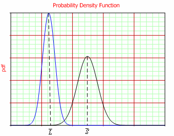
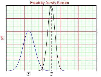
Figures 1-3 show three examples of different relationships between safety margin and loading roughness.
Load and strength distributions that are non-overlapping, as shown in Figure 1, indicate a highly reliable scenario, with narrow distributions, low loading roughness and a large safety margin.

Figure 1: Non-overlapping load and strength distributions
with high SM and low LR
Figure 2 illustrates low loading roughness and low safety margin. In this situation, extreme load will cause failures of weak parts.

Figure 2: Load and strength distributions with low SM and low
LR
Figure 3 is the situation with low safety margin and high loading roughness. This is an undesirable case because an extreme stress will cause a large proportion of the population to fail.

Figure 3: Load and strength distributions with Low SM and
High LR
From the above figures, we can see that there are several possible ways to improve the population reliability: by increasing the safety margin or by decreasing the width of the load and/or strength distribution. Often, increasing the safety margin by increasing the mean strength is expensive; thus, curtailing the load distribution may be preferable because of low expense. Derating is actually one method of load distribution curtailing.
Derating Standards
Several derating guidelines have been issued by military or other agencies, and the following are some examples:
- MIL-STD-975, published by NASA, focuses on selection of parts used in the design and construction of space flight hardware as well as mission-essential ground support equipment.
- MIL-STD-1547, published by the Department of Defense, is targeted to aid in the design, development and fabrication of electronic systems with long life and/or high reliability requirements while operating under the extreme conditions of space and launch vehicles.
- AS4613, published by the U.S. Navy, sets forth derating requirements for the reliable application of electronic and electromechanical parts.
- NAVSEA TE000-AB-GTP-010, published by the U.S. Navy, contains derating requirements and part selection and application information on the ten most commonly used electrical and electronic parts.
- ECSS-Q-30-11A, prepared and maintained under the authority of the Space Components Steering Board in partnership with the European Space Agency, contains derating requirements applicable to electronic, electrical and electromechanical components.
- MSFC-STD-3012, prepared by NASA's Marshall Space Flight Center, sets requirements for electrical, electronic and electromechanical parts selection, management and control for space flight and mission-essential ground support equipment for Marshall Space Flight Center programs.
In addition to the derating standards published by the military, many semiconductor manufacturers such as Freescale and Hitachi provide their own derating guidelines, which can be explored in the datasheets or application notes of electronic parts.
For the same component, the derating parameters in different standards may be different. An example using MIL-STD-975M for a resistor is given below. The software package used is ReliaSoft's Lambda Predict.
Example
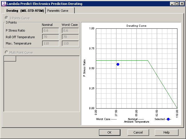
Table 1 gives the properties of the resistor and the derating specifications. Figure 4 is the derating output from Lambda Predict.
Table 1: MIL-STD 975M derating specs for resistor, fixed carbon
| Standard | MIL-STD 975M |
| Component | Resistor, fixed carbon |
| Parameter | Power |
| Derating Specs | 60% up to 70C and further decreasing to 0 at 110C |

Figure 4: Lambda Predict 2 Derating Example for Resistor,
Fixed Carbon
In Figure 4, the green line is the derating curve given by MIL-STD-975M. The blue dot shows the resistors working temperature and power ratio under the defined working condition. For the case shown, the resistor is properly derated since the power ratio is below the derating line for the resistors working temperature. However, if the dot were above the derating curve, the stress under the working condition would not meet the derating requirement given by MIL-STD-975M. This would imply that the resistor would be likely to fail; therefore, changing to a higher-rated resistor or adjusting the operating condition might be needed.
References
[1] OConnor, Patrick D. T., Practical Reliability Engineering, 4th ed., West Sussex, UK: John Wiley Sons, 2002.