Using BlockSim to Analyze a Non-Repairable Standby Function Unit
Standby reliability configurations are widely used in many applications. For mission critical components or function units, standby redundancy can improve the reliability of a system. Take for example a sliding door that can be opened either by a remote controller (electronic) or by pulling the handle (mechanical). The mechanical handle can be thought of as a standby for the remote controller. Many other examples can be found in satellite, missile and medical devices where the reliability requirements are usually very high. In this article, we will explain how to use BlockSim to model a non-repairable system with complex standby function units.
What are Standby Components?
Standby redundancy configurations consist of components that are in one of two states: an active state and a standby state. The following picture shows an example of a BlockSim standby container with one component configured for the active state and another component configured for the standby state.

Each state has an associated failure distribution. When the container is in the active (or operating) mode, it is said to have an active failure distribution. In the standby mode, the container is said to have a quiescent (or dormant) failure distribution. There are three ways to describe standby configurations:
- A hot standby configuration is when both the quiescent and active states have the same failure rate distributions.
- A warm standby configuration is when the failure rate of the standby container is lower in quiescent mode than in active mode.
- A cold standby configuration is when the failure rate of the standby container is zero in quiescent mode (i.e., standby components cannot fail when the container is in standby mode).
BlockSim provides both analytical and simulation results for standby components.
What are Standby Function Units?
A function unit can be described as an assembly or set of components that work together to accomplish a specific function. In some complex systems, standby function units may be used in addition to using individual standby components. In the following example, the standby container contains two function units. The top unit is the active path, while the bottom unit is the standby path. If one of the components in the active path fails, then the active unit will shut down and the standby unit will take over.
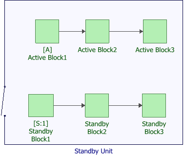
Note that in BlockSim, standby containers can model only series configurations, as shown in the example above. In order to model function units that have parallel or complex reliability configurations, you must use state change triggers instead of standby containers.
Using State Change Triggers to Model Complex Standby Function Units
State change triggers allow you to specify the starting state of a block (i.e., off or on) and its state upon repair, then specify events that will activate and/or deactivate the block during simulation. In BlockSim, maintenance groups are used to trigger the event that causes the state change; therefore, you must first create a maintenance group before you can use state change triggers.
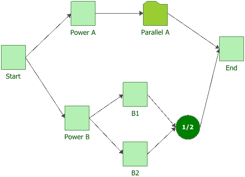
For example, the following diagram shows a starting block that branches out into two paths. Let us assume that the path with the Power A block is the active path, while the path with the Power B block is the standby path. In this scenario, the standby path takes over when Power A fails or if both A1 and A2 blocks fail.

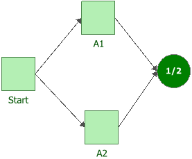
Before we model the scenario, let us first simplify the process by moving the parallel configuration of A1 and A2 into a subdiagram called "Parallel A," as shown next.
We then incorporate the subdiagram into the main diagram, as shown next.
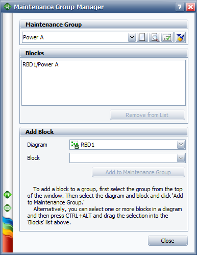
Next, we create a maintenance group for Power A and a separate maintenance group for Parallel A. The following picture shows the maintenance group for Power A, as an example.
Finally, we create a state change trigger for Power B by using the maintenance groups as the triggers, as shown next. Now when Power A or Parallel A fails, it will activate Power B.

You can use the same steps to create state change triggers for the following scenarios:
- When Power A is down, shut down Parallel A. Similarly, if Parallel A is down, shut down Parallel A.
- When Power B is active, activate blocks B1 and B2.
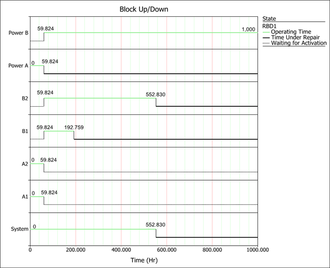
To verify whether the state change triggers are working as planned, run a simulation on the diagram and then create a system up/down plot to track the changes.
For example, the following plot shows that when Power A went down at 59.824 hours, it switched off A1, A2. It also switched on Power B, which switched on B1 and B2.
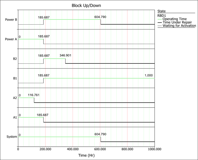
The following plot shows a different scenario in which Parallel A went down at 185.687 hours. It switched off Power A and switched on Power B, which switched on B1 and B2.
Conclusion
In this article, we discussed how to use BlockSim to model a standby system. For a simple standby system, we can use BlockSim's standby container. However, for complex standby systems with parallel subsystems, state change triggers are recommended.