Fault Tree Analysis
This quick subject guide provides an overview of the basic concepts in fault tree analysis (FTA, system analysis) as it applies to system reliability, and offers a directory of some other resources on the subject.
History of Fault Tree Analysis (FTA)
Fault Tree Analysis (FTA) is another technique for reliability and safety analysis. Bell Telephone Laboratories developed the concept in 1962 for the US Air Force for use with the Minuteman system. It was later adopted and extensively applied by the Boeing Company. Fault tree analysis is one of many symbolic "analytical logic techniques" found in operations research and in system reliability. Other techniques include reliability block diagrams (RBDs).
What is a Fault Tree Diagram (FTD)?
Fault tree diagrams (or negative analytical trees) are logic block diagrams that display the state of a system (top event) in terms of the states of its components (basic events). Like reliability block diagrams (RBDs), fault tree diagrams are a graphical design technique, and as such provide an alternative methodology to RBDs.
An FTD is built top-down and in term of events rather than blocks. It uses a graphic "model" of the pathways within a system that can lead to a foreseeable, undesirable loss event (or a failure). The pathways connect contributory events and conditions, using standard logic symbols (AND, OR, etc.). The basic constructs in a fault tree diagram are gates and events, where the events have an identical meaning as a block in an RBD and the gates are the conditions.
Fault Trees and Reliability Block Diagrams
The most fundamental difference between fault tree diagrams and RBDs is that you work in the "success space" in an RBD while you work in the "failure space" in a fault tree. In other words, the RBD looks at success combinations while the fault tree looks at failure combinations. In addition, fault trees have traditionally been used to analyze fixed probabilities (i.e., each event that composes the tree has a fixed probability of occurring) while RBDs may include time-varying distributions for the blocks' success or failure, as well as for other properties such as repair/restoration distributions.
Drawing Fault Trees: Gates and Events
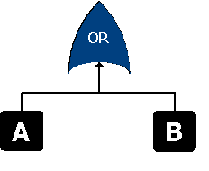
Fault trees are built using gates and events (blocks). The two most commonly used gates in a fault tree are the AND and OR gates. As an example, consider two events (called input events) that can lead to another event (called the output event). If the occurrence of either input event causes the output event to occur, then these input events are connected using an OR gate. Alternatively, if both input events must occur in order for the output event to occur, then they are connected by an AND gate. As a visualization example, consider the simple case of a system composed of two components, A and B, where a failure of either component causes system failure. The system RBD is made up of two blocks in series (see RBD configurations), as shown next:

The fault tree diagram for this system includes two input events connected to an OR gate which is the output event or the "top event"). If the top event is system failure and the two input events are component failures, then this fault tree indicates that the failure of A or B causes the system to fail.

Relationships Between Fault Trees and RBDs
Although the symbols and structures of the two diagram types differ, most of the logical constructions in a fault tree diagram can also be modeled with an RBD. In general, a fault tree can be easily converted to an RBD. It is generally more difficult to convert an RBD into a fault tree, especially if one allows for highly complex configurations. The following table shows gate symbols commonly used in fault tree diagrams and describes their relationship to an RBD. (The term "Classic Fault Tree" refers to the definitions as used in the Fault Tree Handbook (NUREG-0492) by the US Nuclear Regulatory Commission).
|
Table 2: RBD Constructs without a Traditional Fault Tree Equivalent |
|||
| Function | FTA Equivalent | Description | RBD Equivalent |
| Dependency (load sharing) | Not used in classic FTA. | Allows for modeling event dependency (or load sharing). The output event occurs if all input events occur; however, the events are dependent (i.e.m the occurrence of each event affects the probability of occurrence of the other events). | Load sharing parallel configuration |
| True Standby with a quiescent failure distribution | A priority AND gate can be used. However, this does not account for quiescent failure probabilities. | Standby redundancy configurations consist of items that are inactive and available to be called into service when/if the active item fails (i.e., on standby). Items on standby can also fail (quiescent) while waiting to switch. | Standby parallel configuration |
|
Table 3: Traditional Fault Tree Gates without an RBD Equivalent |
|||
| Name of Gate | Classic FTA Symbol | Description | RBD Equivalent |
| XOR |

|
The
output event occurs if exactly one input event occurs. In a
two component system the event does not occur if both or none
of the inputs occur. When modeling system reliability, this implies that the system is successful if none of the components fail or if all of the components fail. |
Cannot be represented and does not apply in terms of system reliability. In system reliability, this would imply that a two-component system would function even if both components have failed. |
Events
The gates in a fault tree are the logic symbols that interconnect contributory events and conditions. An event (or a condition) block in a fault tree is the same as a standard block in an RBD, in that it can have a probability of occurrence (or a distribution function). However, unlike traditional RBDs, where a single graphical representation is utilized to represent the block (or event), fault trees use several graphical block representations. Table 4 discusses these graphical representations.
|
Table 4: Traditional Fault Tree Event Symbols and their RBD Equivalents |
|||
| Primary Event Block | Classic FTA Symbol | Description | RBD Equivalent |
| Basic Event |
|
A basic initiating fault (or failure event). | Block |
| External Event (House Event) |

|
An event that is normally expected to occur. In general, these events can be set to occur or not occur (i.e., they have a fixed probability of 0 or 1). | Block
that cannot fail or that is in a failed state.
|
| Undeveloped Event |

|
An event which is no further developed. It is a basic event that does not need further resolution. | Block |
| Conditioning Event |
|
A specific condition or restriction that can apply to any gate. | Block: Placement of the block will vary depending on the gate applied to. |
|
Table 5: Additional Fault Tree Constructs and their RBD Equivalents |
|||
| Primary Event Block | Classic FTA Symbol | Description | RBD Equivalent |
| Transfer |
|
Indicates a transfer continuation to a sub tree. | Subdiagram block |
Example 1
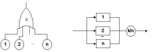
A fault tree diagram with a voting gate and the RBD equivalent.

Example 2
Fault trees and complex RBDs: The best example of a complex reliability block diagram is the so-called bridge. The following RBD represents such a bridge.""

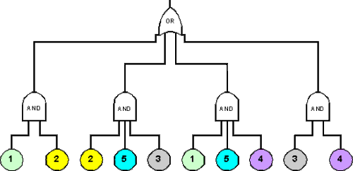
Representation of this bridge as a fault tree diagram requires the utilization of duplicate events, since gates can only represent components in series and parallel. An inspection of this system reveals that any of the following failures will cause the system to fail:
-
Failure of components 1 and 2.
-
Failure of components 3 and 4.
-
Failure of components 1 and 5 and 4.
-
Failure of components 2 and 5 and 3.
In probability terminology, we have:
-
(1 And 2) Or (3 And 4) Or (1 And 5 And 4) Or (2 And 5 And 3).
These sets of events are also called minimal cut sets. It can now be seen how the fault tree can be created by representing the above set of events in the following fault tree.

Conversion of the above fault tree to an RBD (note that components with same name are mirrored blocks).

Additional ReliaSoft Resources and Publications
Additional Resources and Publications on Other Sites
-
Fault Tree Handbook (NUREG-0492)
Systems and Reliability Research, Office of Nuclear Regulatory Research, US Nuclear Regulatory Commission, Washington, DC 20555-0001 -
FAULT TREE ANALYSISA Bibliography from the NASA Scientific and Technical Information (STI) Program. http://ntrs.nasa.gov/archive/nasa/casi.ntrs.nasa.gov/20000070463.pdf
Hyperlinks to third-party websites are provided by Hottinger Bruel & Kjaer Inc. as a convenience to the user. HBK does not control these sites and is not responsible for the content, update or accuracy of these sites. HBK does not endorse or make any representations about the companies, products, or materials accessible through these hyperlinks. If you opt to hyperlink to sites accessible through this site, you do so entirely at your own risk.